YOU ARE LEARNING:
Truth Tables

Truth Tables
Truth tables are used to describe the action of individual gates and simple combinations of gates.
How many types of logic gates do we need to know about?

Which of the following are the correct names of the logic gates in a digital circuit?
You can select multiple answers
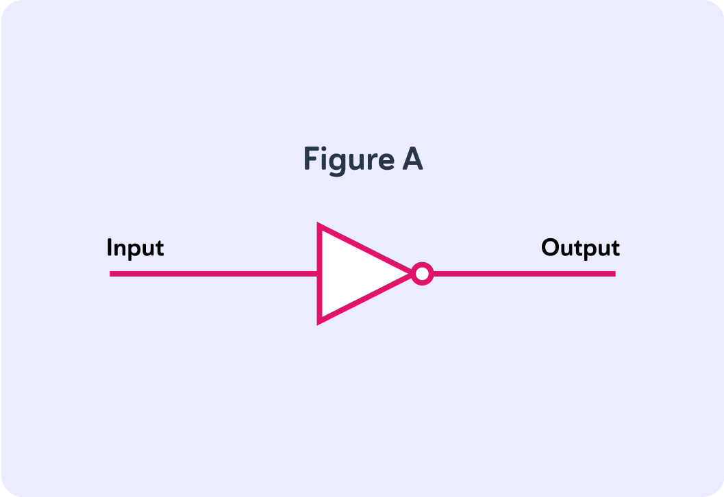
We can represent logic gates with circuit symbols. Which logic gate could be represented by figure A? It has only 1 input.
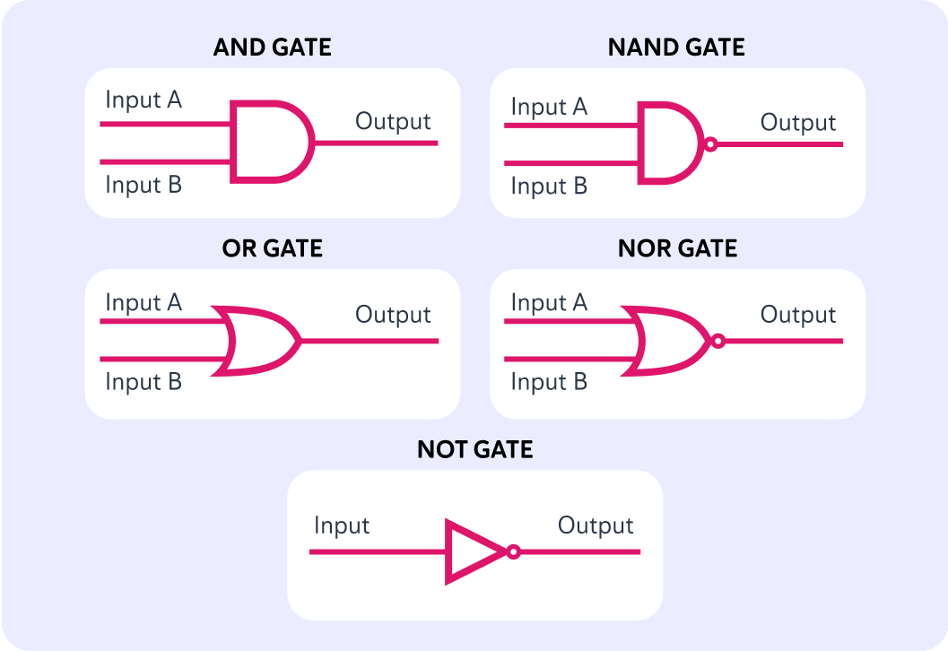
This image shows the different circuit symbols for each of the logic gates.
Note the different shapes along with the inputs and outputs.
Which logic gates are in this circuit?
A) AND gates only B) AND and OR gates only C) AND and OR and NOT gates
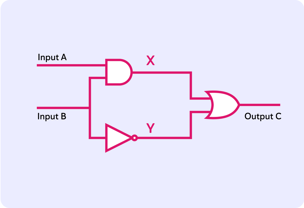
How many possible inputs are there in this circuit?
What logic gate does the wire labelled "Input A" enter?
A) AND gate B) OR gate C) NOT gate
What logic gate does the wire labelled "Input B" enter?
A) NOT gate only B) NOT gate and OR gate C) NOT gate and AND gate
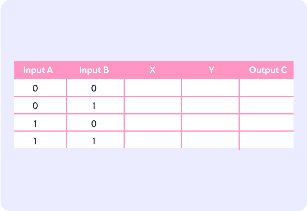
This is the beginning of a truth table, based on the circuit from before. Input A can either be 1 or 0, and input B can either be 1 or 0. How many possible combinations does that give us?
Now, which logic gate does the wire X leave from?
A) AND gate B) OR gate C) NOT gate
Because the X wire goes from an AND gate, it will only carry a signal if the input is one of the four combinations given in this truth table. In which row should we write 1 instead of 0 in the X wire column?
A) The first row B) The second row C) The third row D) The fourth row
The Y wire goes between the NOT gate and the OR gate.
It only takes input from Input B, and it will produce a signal as long as Input B is not 1. That is why it says 1 in the first and third row for the Y wire. The Y wire doesn't care about what it says in the column for Input A.
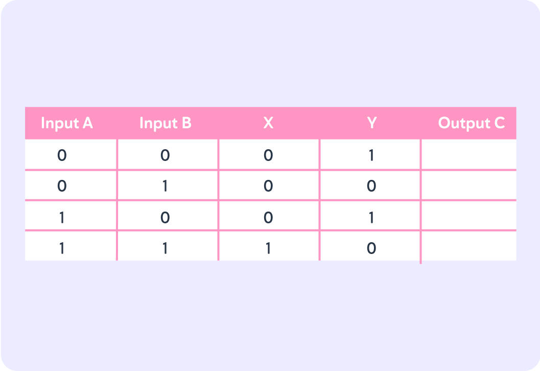
The final logic gate is an OR gate. It takes its input from the X wire and the Y wire to produce output C. There is only 1 row where the final OR gate will produce a 0 instead of a 1. Which row is that?
A) The first row B) The second row C) The third row D) The fourth row
This is the completed truth table.
It shows you how different possible inputs into logic gates will affect the possible output of the whole circuit.
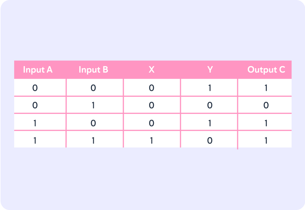
So, a truth table shows the possible outputs for logic gates in circuits depending on the input they receive. To work out a truth table, you need to start with the first logic gate and work your way through the circuit.