YOU ARE LEARNING:
Circuit Diagrams

Circuit Diagrams
This lesson looks at all the different symbols for circuit components and uses them in D.C. circuit diagrams.
When we draw circuit diagrams, the different components are represented with symbols. This avoids having to draw detailed pictures of complicated components, saving us a lot of time!
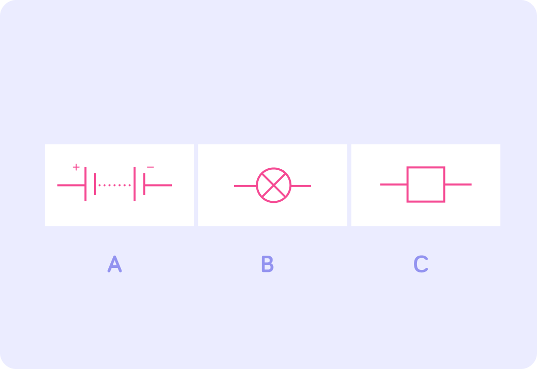
Do you recognise what the circuit symbol is in diagram A?
a) Resistor b) Bulb c) Battery
Answer a, b or c.

Notice that a battery is made up of two parts.
The short line and the longer line make up the symbol for a cell. A battery is made up of multiple cells.
What is shown by the circuit symbol in diagram B?
a) Resistor b) Battery c) Bulb
Answer a, b or c.
So, what is the component labelled C?
To sum up,
The diagram shows the circuit symbols of a battery (A), a bulb (B) and a resistor (C).
We have to remember the positive and negative terminals (the + and the -) when we draw a battery or a cell because they show...
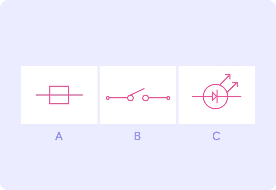
Which of the diagrams shown above do you think is the circuit symbol for a switch? Answer A, B or C.
A switch can either be on or off.
When it is 'off', the switch symbol is open, as seen above. When it is 'on', the switch symbol must be closed, in order to complete the circuit.
Which of the diagrams shown above do you think represents a fuse? Answer A, B or C.
So, which diagram represents a light-emitting diode or LED? Answer A, B or C.
To sum up,
The image above shows the circuit symbols for a fuse (A), a switch (B) and an LED (C).
Which component is shown by the symbol in diagram A?
a) Thermistor b) Variable resistor c) Battery
Answer a, b or c.
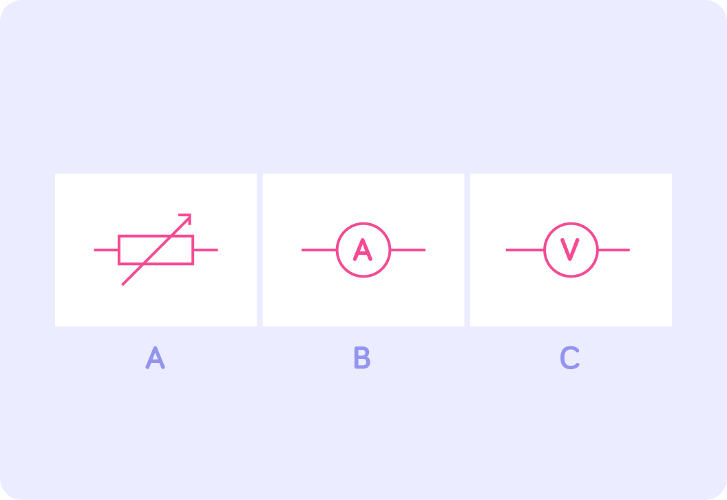
What is the name of the symbol in diagram B? HINT: It measures the current in a circuit.
Finally, can you remember the name of the symbol in diagram C? HINT: It measures the potential difference or voltage in a circuit.
To sum up
The three diagrams show the circuit symbols for a variable resistor (A), an ammeter (B) and a voltmeter (C).
What do you think might be depicted in diagram A? Remember that arrows like that show rays of light.
a) Thermistor b) LDR c) Diode
Answer a, b or c.
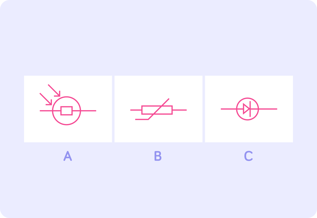
What do you think diagram C represents? The triangle plays a similar role to the "give way" road signs.
a) Thermistor b) LDR c) Diode
Answer a, b or c.
So which diagram represents a thermistor? Answer A, B or C.
To sum up,
The image showed the circuit symbols for a light-emitting diode or LDR (A), a thermistor (B) and a diode (C).
A magnetising coil strengthens or weakens the magnetic field, depending on the number of coils. Which symbol represents a magnetising coil? Answer A, B or C.
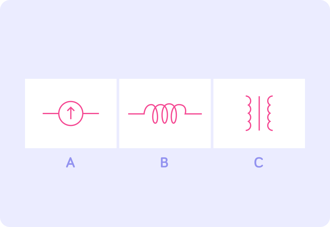
A galvanometer is used for measuring small amounts of electrical current. Which symbol do you think might represent a galvanometer? Answer A, B or C.
Finally, transformers can either raise or lower voltage. Which symbol represents a transformer? Answer A, B or C.
To sum up,
The image showed the circuit symbols for a galvanometer (A), a magnetising coil (B) and a transformer (C).
We represent wires in a circuit diagram with lines. These lines are always ________.
Take a look at this simple circuit diagram. It contains 4 components. Can you name one of them?
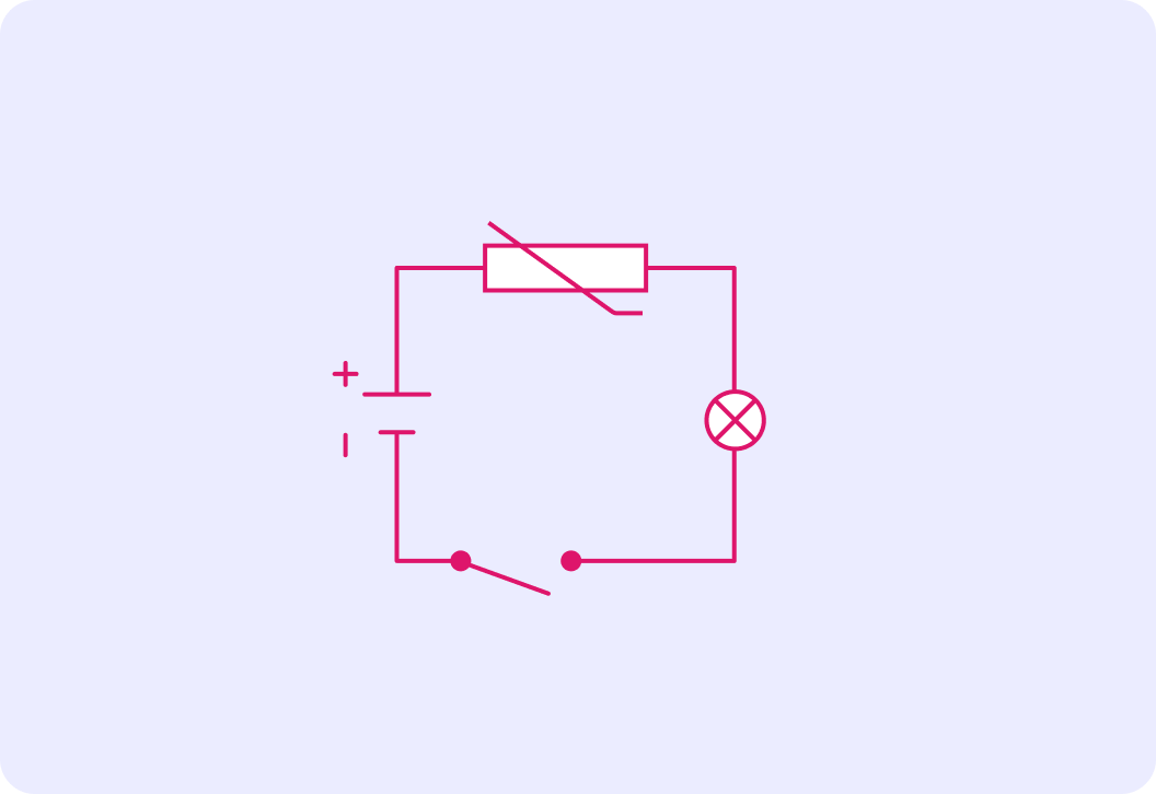
Is the circuit "open" or "closed"?
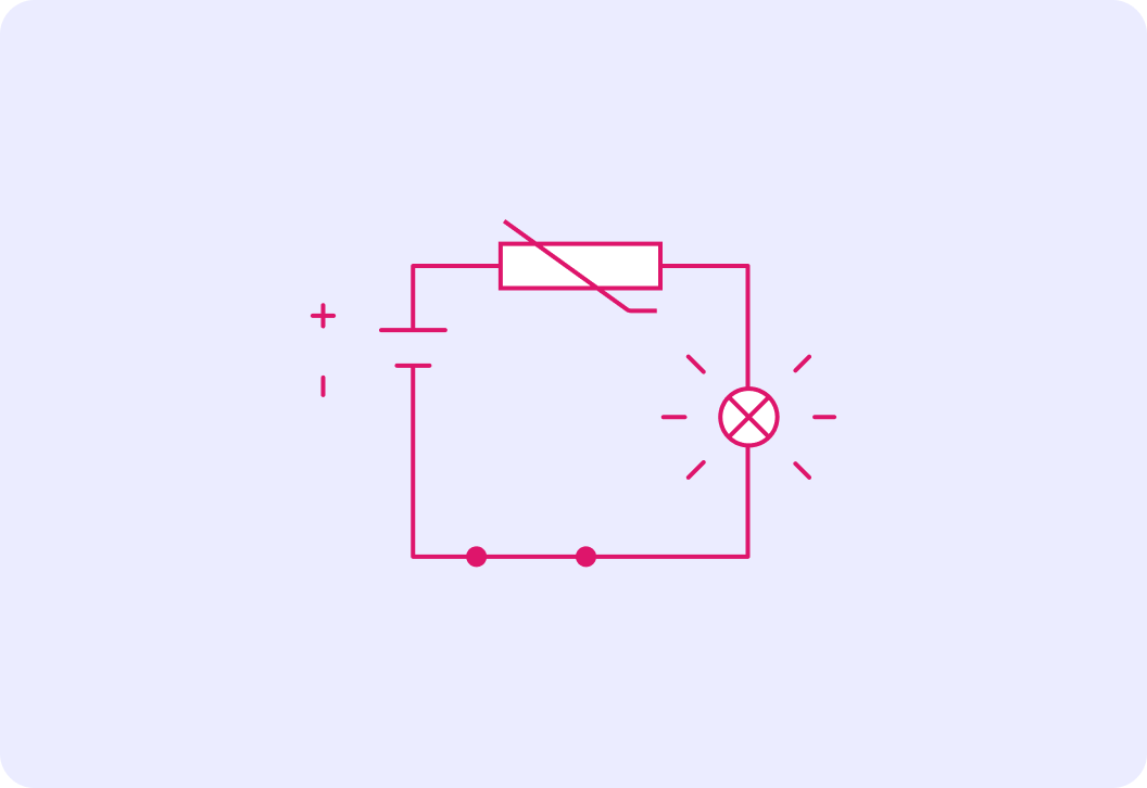
Here the switch is on, so the circuit is complete.
Current is now able to flow around the circuit and switch the bulb on.
Does it matter where the switch is placed? Answer yes or no.
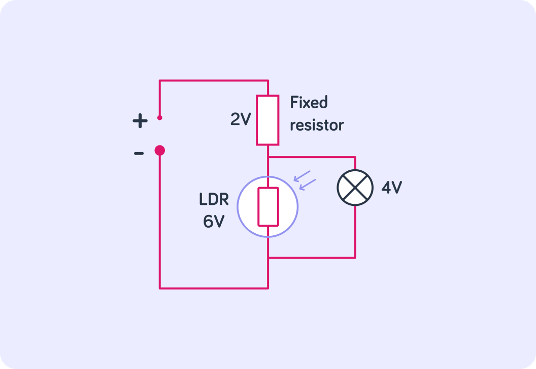
Here we have another slightly more complicated circuit.
It shows how an LDR works, for example for a street lamp. The bulb is connected in parallel to the circuit. You will learn more about that in later lessons.